What is topology in computer networking? Network topology is the way routers, switches, computers, WiFi devices, and other equipment connect to form a network. It describes both the physical connections between devices and the paths data takes as it moves through them.
For homeowners, topology helps explain frustrating problems that an internet speed test alone cannot solve. Your WiFi may work perfectly in the living room but drop in an upstairs bedroom. A garage camera might disconnect every evening, while the computer beside your router stays connected.
These problems often come down to how the network is arranged. Once you understand the layout, you can make better decisions about router placement, Ethernet wiring, WiFi extenders, and mesh systems without replacing equipment unnecessarily.
What Is Topology in Computer Networking?
Network topology describes how devices are connected and how they communicate across a network.
In a typical home, the router connects to your internet service and provides access to computers, phones, smart TVs, cameras, and other devices.
Some equipment connects directly to the router through Ethernet cables. Other devices connect wirelessly. You might also have a WiFi extender in the hallway or an Ethernet switch in the home office.
Those connections form your network topology.
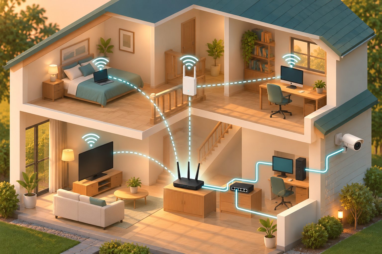
Consider a two-story house with these devices:
-
A router in the downstairs living room.
-
A desktop computer connected through Ethernet.
-
A smart TV using the router's WiFi.
-
A WiFi extender on the upstairs landing.
-
Two bedrooms connecting through the extender.
-
An outdoor camera connecting from the garage.
The devices belong to the same home network, but they do not all use the same connection path.
If the router stops working, the household may lose internet access.
If the upstairs extender disconnects, the bedrooms may lose their connection while the downstairs computer continues working.
If the camera is too far from the extender, it may lose its connection even when the extender itself is operating normally.
Knowing which device depends on which connection tells you where to start troubleshooting.
Why Network Topology Matters at Home
A fast broadband connection cannot compensate for every weakness inside a home network.
Suppose your internet plan provides enough bandwidth for several simultaneous video streams. That does not mean a laptop will receive the same performance in every room.
The laptop's connection still depends on its distance from the access point, the building materials between them, wireless interference, and the quality of the network path back to the router.
Topology affects several everyday tasks.
Video calls
A laptop in an upstairs office may connect through a WiFi extender. If the extender has an unreliable connection to the router, the call can freeze even when the broadband service is functioning normally.
Security cameras
An outdoor camera may show a strong WiFi connection during installation but disconnect after it is mounted behind a thick exterior wall.
The camera's physical location and the nearest access point matter.
Streaming televisions
A television connected through Ethernet may provide more consistent playback than one relying on weak WiFi.
However, if several devices share a slower network uplink, that connection can still become congested.
Smart home devices
A smart plug might connect to WiFi but fail to communicate with another device because the two are separated by guest network isolation.
That is a network configuration issue rather than a signal problem.
Your goal is to identify whether a problem comes from the physical connection, the logical network configuration, or the internet service itself.
How to Identify Your Current Network Topology
You can map a home network without special software.
Start with the equipment that connects to your internet provider.
This may be a cable modem, fiber Optical Network Terminal, or combined provider gateway.
Find the router connected to it. The router usually provides your main WiFi network and Ethernet LAN ports.
Next, locate any additional networking equipment:
-
Ethernet switches.
-
WiFi extenders.
-
Mesh WiFi nodes.
-
Wireless access points.
-
Network-connected security cameras.
-
Smart home hubs.
-
Computers and televisions using Ethernet.
Take a sheet of paper and draw the rooms in your home.
Mark the router first. Add the other networking devices and draw their connections.
Use solid lines for Ethernet cables and dotted lines for wireless connections.
For example, your diagram might show the router connected by Ethernet to an office switch. The switch connects to a desktop computer and printer.
Upstairs, an extender connects wirelessly to the router and serves two bedrooms.
That drawing immediately reveals a useful detail: every upstairs device depends on the wireless connection between the extender and the router.
If that connection is weak, replacing the laptop or moving the television will not fix the underlying problem.
Keep the diagram simple. You only need enough information to identify the equipment and the connections between it.
Physical Topology vs Logical Topology
Network topology has two main forms: Physical Topology and Logical Topology.
Physical topology describes where equipment is located and how it is connected.
Logical topology describes how data travels through the network and which devices are allowed to communicate.
Both matter when troubleshooting.
A camera can have excellent WiFi reception and still be unreachable from your phone. A desktop computer can have a working Ethernet connection but no internet access.
These situations may involve logical network settings rather than damaged cables or weak signals.
What Is Physical Topology?
Physical topology refers to the actual arrangement of network hardware.
It includes the location and connections of routers, switches, cables, wireless access points, and other networking equipment.
Imagine a home office with an Ethernet cable running from the router to a switch under the desk.
The switch connects to a desktop computer, a printer, and network storage.
That is a physical arrangement you can inspect.
If the cable between the router and the office switch becomes disconnected, every device relying on that uplink may lose access to the rest of the home network.
The computer and printer may still communicate with each other through the switch, provided their local network settings allow it.
Now imagine moving the office equipment to another room and running a different cable.
You have changed the physical topology.
Physical connections affect performance because they introduce practical limits.
Ethernet cables have supported distance limits. Wireless signals weaken through walls and floors. A router hidden behind metal shelving may provide poorer coverage than the same router placed in an open location.
Even the connection between two mesh nodes can become unreliable if one node is moved too far away.
What Is Logical Topology?
Logical topology describes the paths data follows and the network rules that determine communication.
It includes settings and functions such as:
-
IP addressing.
-
Routing.
-
DHCP address assignment.
-
Network subnets.
-
VLANs.
-
Guest network isolation.
-
Firewall rules.
Most homeowners never need to configure all these features.
Still, understanding a few of them helps when a device appears connected but does not behave as expected.
For example, two computers connected to the same Ethernet switch can exchange local traffic through that switch when their network configuration permits it.
Their traffic does not normally need to travel to the internet and back.
However, if one computer belongs to an isolated network, communication may be blocked even though the cables are connected correctly.
The physical topology shows that a connection exists.
The logical topology determines whether the communication is permitted and how it reaches its destination.
A Practical Example: A Camera That Works but Cannot Be Viewed
Suppose you install a WiFi security camera in your garage.
The camera connects successfully, and its indicator shows that it has network access.
However, your phone cannot discover it through the manufacturer's app during local setup.
Moving the camera closer to the router may not solve the problem.
First, check which network each device is using.
Your phone might be connected to the main WiFi network while the camera is connected to a separate guest network.
Many routers restrict communication between guest devices and equipment on the main network.
Some also prevent wireless clients from communicating directly with one another.
These settings are useful for limiting access, but they can interfere with local device discovery.
To investigate:
-
Open the WiFi settings on your phone.
-
Confirm the network name.
-
Check the camera's network information through its setup interface, if available.
-
Open the router's connected-device list.
-
Look for guest network or client isolation settings.
-
Confirm that the devices are using a network arrangement supported by the camera.
Do not disable every firewall or isolation feature simply to make the camera appear.
Check the camera's connection requirements and adjust only the relevant settings.
This is a useful example of logical topology: the wireless signal can be strong while the network configuration prevents the desired communication.
Common Types of Network Topologies
The main types of network topology include star, mesh, tree, bus, and ring.
These terms describe different ways of arranging connections.
In a modern home, star connections are common for wired devices. Mesh and hybrid arrangements are useful when WiFi must cover several rooms or floors.
Bus and ring topologies remain useful concepts, although they are uncommon in ordinary home installations.
Star Topology
Star Topology connects devices to a central networking device, usually an Ethernet switch or a router with built-in switch ports.
Picture a router with Ethernet cables running to a desktop computer, smart TV, and gaming console.
Each device has a separate connection to the central equipment.
This arrangement is common because it is straightforward to install and troubleshoot.
If the computer's cable fails, the television and gaming console can usually continue communicating.
You can test the problem by changing the computer's cable or switch port without disturbing the other devices.
Advantages of Star Topology
A star network provides several practical benefits.
Independent wired connections
Each wired device has its own physical link to the central switch.
One damaged device cable does not normally disconnect everything else.
Straightforward troubleshooting
If a computer loses its connection, you can check its cable, network port, and corresponding switch indicator.
You do not need to inspect every device in the house.
Simple expansion
An Ethernet switch can provide more ports when the router's built-in connections are insufficient.
Useful performance for stationary equipment
Wired connections avoid many wireless problems caused by distance, thick walls, and interference.
A star layout works particularly well for home offices, entertainment centers, and wired security systems.
Limitations of Star Topology
The central equipment is an important dependency.
If an Ethernet switch fails, devices connected through it lose access to the rest of the network.
If the main router fails, internet connectivity and routing functions may stop.
Some devices connected through the same working switch may still communicate locally.
A wired star network also requires cables.
Running Ethernet through finished walls can be inconvenient, especially in rented properties.
For rooms without available cable routes, wireless access may be more practical.
When Star Topology Makes Sense
Choose a star-style wired arrangement when you have several devices that remain in fixed positions.
Typical examples include:
-
A desktop computer in a home office.
-
A smart TV beside the router.
-
A gaming console in an entertainment center.
-
A network printer.
-
A compatible Ethernet security camera.
You may already have the necessary central equipment.
Many home routers include several LAN ports that function as a small Ethernet switch.
Add an external switch only when you need more connections or a separate group of wired ports in another room.
Mesh Topology
Mesh Topology allows network nodes to communicate through available connections, potentially providing more than one path between parts of the network.
In a full mesh, every node connects directly to every other node.
In a partial mesh, only certain nodes have multiple connections.
Consumer mesh WiFi systems typically use coordinated wireless nodes. Their exact connection arrangement depends on the product, installation, and available backhaul.
Not every mesh system creates a direct connection between every node.
How Mesh WiFi Works in a Home
Consider a two-story house with a router downstairs.
A single router may struggle to provide usable coverage in the upstairs bedrooms.
A compatible mesh system can use additional nodes to serve those areas.
You might place the main node near the broadband connection, another near the staircase, and a third in a suitable upstairs location.
Each node provides wireless coverage.
Compatible mesh systems also coordinate certain network functions, including how connected devices are encouraged to move between access points.
For example, when you carry your phone upstairs, the network may help it move toward a better connection.
The phone still participates in the roaming decision, so a seamless transition is not guaranteed.
Node placement matters.
An upstairs node cannot deliver reliable performance if its connection to the rest of the mesh is consistently weak.
What Is Backhaul?
Backhaul is the connection that carries traffic between a mesh node or wireless access point and the main network.
There are two common approaches.
Wireless backhaul
The node communicates with the main network over WiFi.
This avoids running Ethernet cables, but performance depends on signal quality, wireless capacity, and interference.
Wired backhaul
The node connects to the network using Ethernet.
This removes the need for that particular connection to rely on WiFi.
Wired backhaul can provide more predictable performance, especially when thick floors or walls make wireless communication difficult.
A mesh system may support both methods.
Before buying additional nodes, check whether the model supports the backhaul arrangement you want.
Advantages and Limitations of Mesh Topology
Mesh WiFi is useful when a property needs several wireless coverage points.
It can be convenient in larger homes where one router leaves multiple weak areas.
However, adding nodes does not automatically improve performance.
Nodes placed too close together may create unnecessary wireless contention.
Nodes placed too far apart may have unreliable backhaul connections.
A mesh node beside the garage can provide a strong local signal to a camera while still having a poor connection to the main router.
That distinction matters during troubleshooting.
Mesh systems can also be more expensive than a single router and extender.
Choose one when the coverage requirements justify several coordinated wireless nodes.
Mesh WiFi vs a WiFi Extender
A Wi-Fi Extender is commonly used to improve coverage in one weak area.
It receives an existing wireless connection and provides coverage farther from the router.
A mesh system uses compatible nodes designed to operate together.
Some extenders support mesh features when paired with compatible routers, but a conventional extender does not automatically become part of a coordinated mesh network.
For a single weak bedroom, a properly placed extender may be enough.
For several problem areas, compare a mesh system with additional wired access points.
Whichever option you choose, the connection back to the router must be reliable.
Tree and Hybrid Topologies
Tree Topology connects network devices in a branching structure.
One central device connects to another device, which then connects to several more.
Hybrid Topology combines different network arrangements.
Many real home networks are hybrid networks because they use both wired and wireless connections.
A Two-Story Home Example
Imagine a router downstairs and a home office upstairs.
An Ethernet cable runs from the router to an upstairs Ethernet switch.
The switch connects to a desktop computer, smart TV, network storage device, and wireless access point.
The router also provides WiFi to devices downstairs.
The overall layout resembles a tree.
The router connects to an upstairs branch, and the upstairs switch serves several devices.
Within that branch, the wired devices use star connections.
This arrangement can be easier to maintain than installing separate long cables from every upstairs device back to the router.
It also gives the upstairs access point a wired connection to the main network.
Why Hybrid Networks Are Common
Households use equipment with different connection requirements.
A phone needs wireless access.
A desktop computer can use Ethernet.
A smart TV may support either option.
An outdoor camera may use WiFi, Ethernet, or a dedicated connection method depending on its design.
A hybrid network lets you choose an appropriate connection for each device.
For example, you might use:
-
Ethernet for the home office.
-
WiFi for phones and tablets.
-
A wired access point upstairs.
-
A WiFi extender for one distant bedroom.
-
A suitable dedicated connection for an outdoor camera.
The key is to avoid introducing unnecessary weak links.
If the upstairs devices all depend on one poor wireless connection, that link may restrict the entire upstairs network.
Bus and Ring Topologies
Bus and Ring Topologies appear frequently in introductory computer networking terms, but they are not typical choices for a modern home network.
Understanding them is useful because they explain how network designs have evolved.
Bus Topology
A traditional bus topology connects devices along a shared communication medium.
Older Ethernet installations sometimes used coaxial cable in this arrangement.
Traffic from multiple devices shared the same cable segment.
Damage to the shared medium or its termination could disrupt several devices.
Modern switched Ethernet networks generally use separate connections to switches instead.
Connecting several devices to one Ethernet switch does not create a traditional bus topology.
Each device has its own link to the switch.
Ring Topology
A ring topology connects network devices in a closed loop.
Depending on the technology, information travels through the ring according to a defined communication method.
Ring arrangements have been used in specialized networking systems.
They are not normally needed in residential WiFi networks.
Do not connect Ethernet switches in a loop without equipment and configurations designed to manage it.
An unmanaged Ethernet loop can cause repeated frame forwarding and broadcast storms, potentially making the local network unusable.
For most homes, a star or carefully planned hybrid arrangement is easier to maintain.
Hardware and Software Networking Components

Your network topology depends on the equipment you install and the software controlling it.
Most home networks use a small number of hardware components.
Knowing their jobs makes it easier to identify which device to adjust when something stops working.
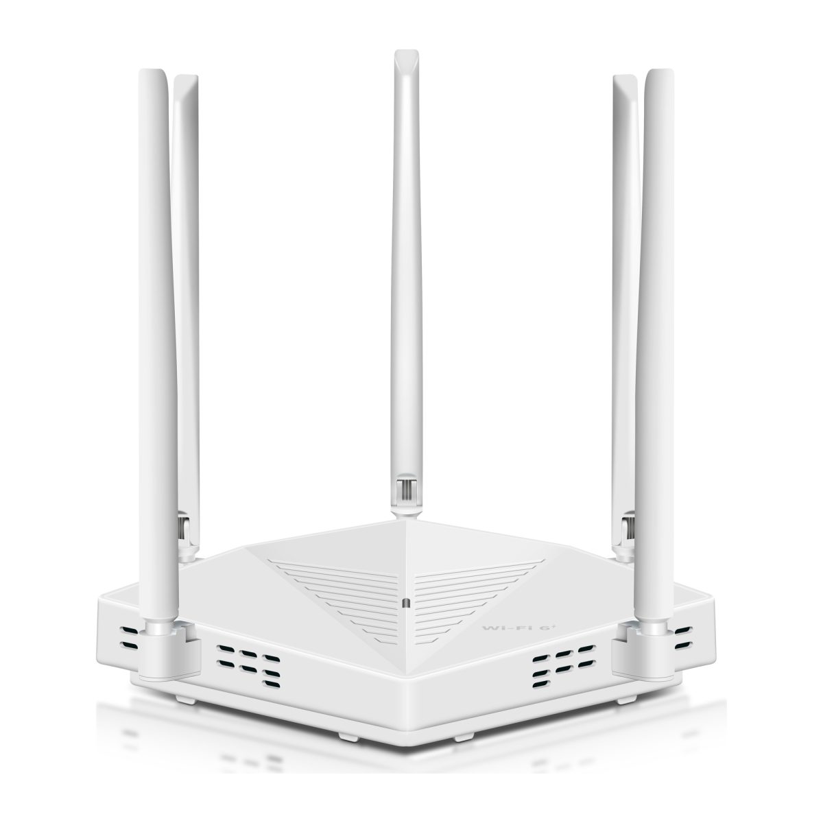
Router: Connecting Your Home to Other Networks
A router connects your home network to other networks, including the internet.
Consumer routers commonly include WiFi, Ethernet LAN ports, a firewall, and DHCP services for assigning local IP addresses.
When a laptop opens a website, the router forwards the required traffic toward the internet.
When two computers communicate through the same Ethernet switch and local network, their traffic may remain within the local network.
If you are considering a replacement router, check what is actually limiting the network.
A newer router may help if the existing model cannot support the wireless capabilities or device load you need.
It will not necessarily solve a dead zone caused by several concrete walls.
Before replacing equipment, use this practical router buyer guide to compare features that matter for home use.
Ethernet Switch: Adding Wired Connections
An Ethernet Switch connects multiple wired devices within a local network.
It is useful when you have more Ethernet devices than available router LAN ports.
For example, one Ethernet cable may run from the router to an upstairs office.
Connect that cable to a switch, and you can attach several wired devices in the office.
For a straightforward home setup, an unmanaged Gigabit Ethernet switch is often sufficient.
Basic installation looks like this:
-
Connect the switch to power.
-
Run an Ethernet cable from a router LAN port to a suitable switch port.
-
Connect your computers and other wired devices.
-
Check the port link indicators.
-
Confirm that the devices can access the intended network resources.
Many unmanaged switches need no configuration.
Remember that all devices using the switch's uplink share that connection when communicating with equipment beyond the switch.
A slow uplink can become a bottleneck even when individual device ports support higher speeds.
Wireless Access Point: Providing WiFi Through a Wired Network
A wireless access point provides WiFi connectivity to an existing network.
It commonly connects to the router or an Ethernet switch through a cable.
This makes it useful for areas where WiFi coverage is poor but Ethernet wiring is available.
Suppose your upstairs office has a wall Ethernet outlet connected to the downstairs router.
A compatible access point can use that connection to provide WiFi upstairs.
The connection back to the router no longer depends on a wireless signal passing through the floor.
Some routers and extenders include an Access Point mode.
Use the appropriate mode when you want additional WiFi coverage without creating a second routed network.
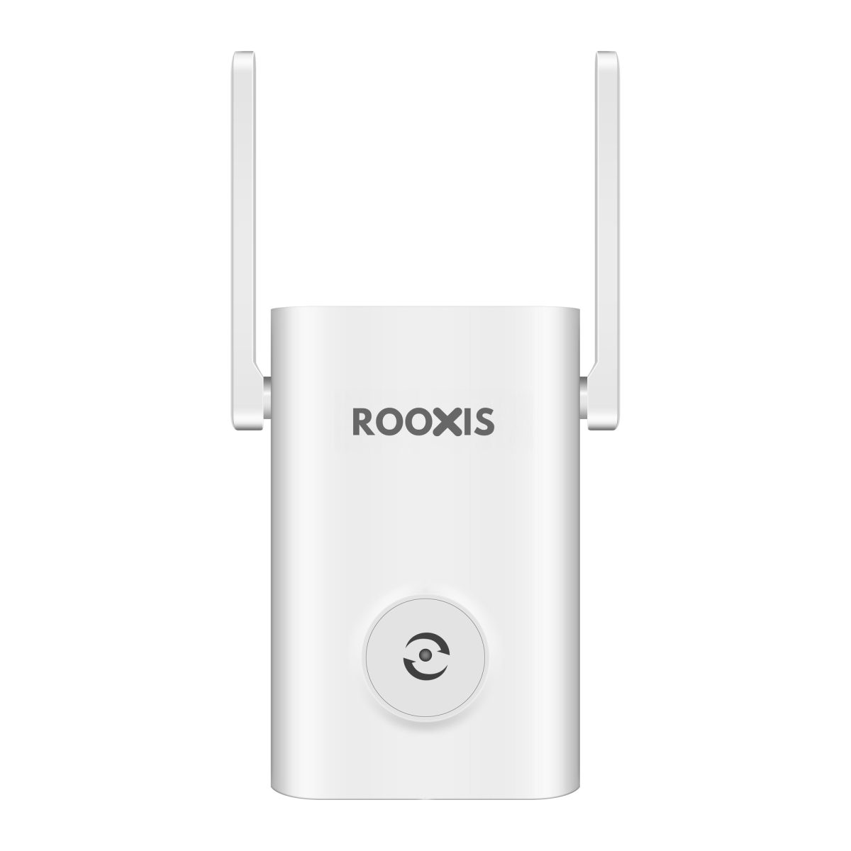
WiFi Extender: Reaching a Weak Area
A WiFi extender receives an existing wireless signal and extends coverage into another area.
It can help when one room has weak WiFi but a nearby hallway still receives a reliable connection.
The extender needs a usable signal from the router.
Putting it inside a complete dead zone rarely helps.
For example, if the upstairs bedroom has almost no WiFi, try positioning the extender on the landing where the main router's signal is still stable.
Then test the connection from the bedroom.
A ROOXIS WiFi extender may be suitable for this kind of targeted coverage problem, provided its operating modes and capabilities match your network.
For larger properties, the best wifi extender for a large house guide can help you decide when a single extender is reasonable and when another approach is better.
Modem and Optical Network Terminal
A modem connects your router to certain broadband services, such as cable internet.
A fiber connection commonly uses an Optical Network Terminal, or ONT.
Some providers supply a combined gateway that performs several functions.
Knowing what you have matters when adding another router.
If the provider gateway already performs routing and you connect a second router behind it, you may create a double NAT arrangement.
This can complicate certain games, remote connections, and device discovery.
If you only need additional WiFi coverage, a supported Access Point mode may be more appropriate than operating a second router as another gateway.
Networking Software and Firmware
Hardware provides the connections, while software controls much of the communication.
Router firmware manages wireless settings, routing, security features, and other network functions.
Your computer and phone also use network drivers and operating system settings to connect.
When troubleshooting, check:
-
Whether the router firmware is current.
-
Whether the device joined the intended WiFi network.
-
Whether DHCP assigned a valid local IP address.
-
Whether guest network settings restrict communication.
-
Whether the router supports the device's wireless requirements.
-
Whether the access point or extender is using the correct operating mode.
Avoid changing multiple settings at once.
If you change the WiFi channel, security mode, and network name together, you may not know which change fixed the problem or caused a new one.
Make one adjustment and test before continuing.
Types of Computer Networking Cables and Connectivity
Ethernet cables form the wired connections in many home network layouts.
The most relevant types of computer networking cables include Cat5e, Cat6, and Cat6a twisted-pair cables.
You may also encounter coaxial cables for certain broadband connections and fiber-optic cables for internet service or specialized network links.
Choosing a cable depends on the connection speed, distance, installation conditions, and devices at each end.
Cat5e Cable
Cat5e is common in residential Ethernet installations.
Properly installed Cat5e cabling supports Gigabit Ethernet over standard channel distances up to 100 meters.
For many homes, this is sufficient.
If your home already has Cat5e cables inside the walls, do not assume they need replacement.
First, check whether the cables are properly terminated and whether the network ports are negotiating the expected speed.
A damaged connector or poorly terminated wall outlet can cause problems even when the cable category is suitable.
Cat6 Cable
Cat6 Cable has improved specifications for signal performance compared with Cat5e.
It supports Gigabit Ethernet over standard channel distances up to 100 meters.
It can also support 10 Gigabit Ethernet over shorter runs under suitable conditions.
Cat6 is a practical choice for new home Ethernet installations when the price and installation requirements are reasonable.
However, replacing a functioning Cat5e cable with Cat6 will not automatically improve internet speed.
If the router and connected device both use Gigabit Ethernet ports, changing the cable category alone does not make those ports operate faster.
Cat6a Cable
Cat6a supports 10 Gigabit Ethernet over standard channel distances up to 100 meters when installed correctly.
It can be useful for more demanding wired networks.
However, Cat6a cable is often thicker and less flexible than Cat5e or Cat6.
That can make installation more difficult in tight conduit or crowded wall boxes.
For ordinary internet browsing, video streaming, and home office work, you may not need Cat6a.
Consider it when planning a wired network with specific higher-speed requirements.
Ethernet Cable Comparison
| Cable type | Typical supported capability | Suitable home uses |
|---|---|---|
| Cat5e | Gigabit Ethernet up to 100 meters | Existing home wiring, computers, televisions |
| Cat6 | Gigabit Ethernet up to 100 meters, higher speeds over suitable shorter runs | New wiring, switches, access points |
| Cat6a | 10 Gigabit Ethernet up to 100 meters | Higher-speed wired networks |
These capabilities assume properly installed cabling and compatible network equipment.
Check the actual Ethernet port specifications before purchasing expensive cables.
A device with a 100 Mbps Ethernet port remains limited by that port, even when connected using Cat6a.
Wired vs Wireless Connections
Ethernet is useful for stationary devices that need reliable connectivity.
A desktop computer, smart TV, or gaming console can often benefit from a wired connection.
WiFi is better suited to portable equipment and locations where cabling is impractical.
However, wireless performance changes with distance, interference, and building materials.
A laptop sitting beside the router may connect at a much higher wireless rate than the same laptop in an upstairs bedroom.
A WiFi extender introduces another important consideration.
The device may have a strong connection to the extender, but the extender still needs to communicate with the router.
If that connection is weak, the whole path can perform poorly.
Use Ethernet for important stationary connections where practical.
Reserve WiFi for devices that need mobility or cannot reasonably be wired.
How Bandwidth Affects Your Layout
Bandwidth describes the capacity of a connection to carry data.
Different parts of your network can have different capacities.
Your internet service has its own speed limits.
Ethernet ports have supported link speeds.
Wireless connections have negotiated link rates that change with conditions.
The actual performance of a task depends on the relevant path.
Suppose your office computer connects to a Gigabit Ethernet switch.
However, the switch connects to the router through a 100 Mbps uplink.
Traffic passing through that uplink cannot exceed its capacity, even though the computer's direct connection to the switch is faster.
A similar limitation can occur with a wireless extender.
Your phone may report a strong connection to the extender while the extender's connection to the router is slow.
When troubleshooting poor speed, check the complete path.
Do not judge performance using only the WiFi signal bars or the highest speed printed on the router's packaging.
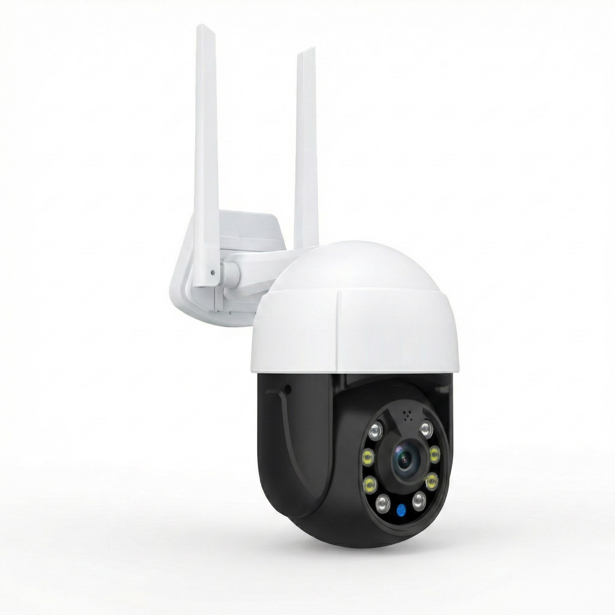
Ethernet and Outdoor Security Cameras
Outdoor cameras often reveal weaknesses in a home network.
A camera mounted behind brick, concrete, or metal may have a much poorer connection than a phone tested inside the nearest room.
If a camera supports Ethernet, a suitable wired installation can provide a more predictable connection.
Some models support Power over Ethernet, or PoE, which allows compatible equipment to provide data and power over the Ethernet cable.
PoE requires the correct power standard and compatible devices.
Do not assume that every camera with an Ethernet port supports PoE.
For outdoor cable runs, choose materials and installation methods suitable for moisture, sunlight, and the surrounding electrical environment.
Connections between separate buildings require additional care because of grounding and electrical hazards. Fiber or a properly designed wireless link may be a better choice in some situations.
If your camera only supports WiFi, test it at the final mounting position before drilling holes.
Check whether its live view opens reliably and whether it maintains a connection during normal operation.
If the signal is weak, improving the nearby wireless coverage may be more effective than replacing the camera.
Selecting the Best Network Layout for Your Home
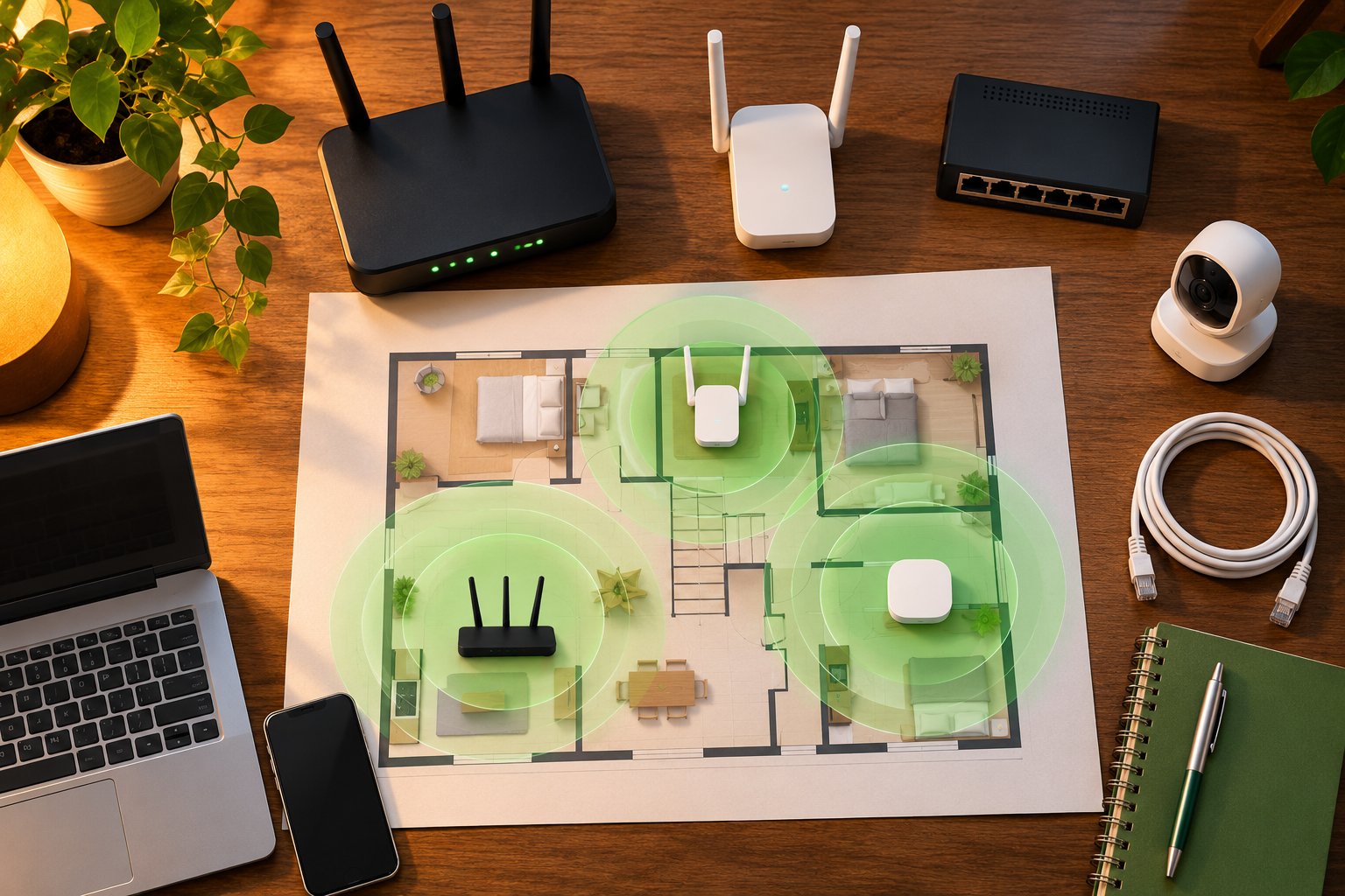
The best home network topology is the simplest arrangement that provides reliable connections where you actually need them.
A one-bedroom apartment may work perfectly with a single router.
A two-story home with a garage camera and upstairs office may need an Ethernet switch, an additional access point, or a mesh system.
Choose equipment according to the problem, not the number of devices advertised on the box.
Step 1: Map Your Current Connections
Start with a rough floor plan.
Mark the location of your main router, modem or ONT, switches, access points, extenders, and mesh nodes.
Then mark the devices that matter most.
These might include:
-
A computer used for video calls.
-
A television used for streaming.
-
A gaming console.
-
Indoor and outdoor security cameras.
-
Smart home hubs.
-
Devices used in upstairs bedrooms.
Draw the connections between them.
Where possible, use your router's management interface to identify connected devices.
Some routers show which access point a device uses or whether it is connected through Ethernet, 2.4 GHz WiFi, or 5 GHz WiFi.
That information can help identify an unexpected connection.
For example, a laptop upstairs might still be connected to the downstairs router even though a nearby extender offers a stronger signal.
Step 2: Test the Existing Network Before Buying Equipment
Test the connection close to the main router first.
Then use the same phone or laptop in the rooms where you notice problems.
Record whether the connection remains stable and whether normal activities work.
You can also use an internet speed test as one piece of evidence.
However, a speed test measures more than your local WiFi. Internet congestion, the test server, and other network traffic can affect the result.
For a useful comparison, test under similar conditions.
If possible, connect a computer directly to the router through Ethernet.
If wired performance is also poor, investigate the broadband connection, router, and cabling.
If wired performance is normal but WiFi fails upstairs, focus on wireless coverage and topology.
Step 3: Choose the Topology That Matches the Problem
| Home situation | Practical starting layout | Why it makes sense |
|---|---|---|
| Small apartment | Single router with star-style connections | Fewer rooms and shorter wireless distances |
| Home office with several wired devices | Router and Ethernet switch | Dedicated wired connections |
| One weak bedroom | Router and properly placed WiFi extender | Targeted coverage improvement |
| Two-story home with Ethernet wiring | Router and wired access point | Reliable connection between floors |
| Large home with several weak areas | Compatible mesh system or wired access points | Multiple coordinated coverage points |
| Home with wired cameras | Router, switch, and compatible camera cabling | Stable stationary connections |
| Detached garage or garden office | Suitable wired or dedicated wireless link | A more dependable connection to a distant location |
Treat this as a starting point.
A small house with thick stone walls may need more access points than a larger open-plan property.
Construction materials and connection paths often matter more than floor area.
Step 4: Check Router Placement Before Changing Topology
Before buying another networking device, inspect the router's location.
Is it sitting inside a television cabinet?
Is it tucked behind a metal filing cabinet?
Is it installed at the far end of the house even though most devices are elsewhere?
These positions can restrict wireless coverage.
Try placing the router in a more open location, away from large metal objects and dense obstructions.
If the broadband connection enters the house near an outside wall, an Ethernet cable may allow the router to be placed somewhere more useful.
Keep power, ventilation, and safe cable routing in mind.
For practical placement guidance, see the ROOXIS router placement tips.
Test the connection again after moving the router.
If the weak room improves enough for normal use, you may not need additional equipment.
Step 5: Add Wired Connections Where They Make Sense
If your home already has Ethernet wiring, use it for important stationary devices.
A desktop computer or television connected through Ethernet no longer depends on WiFi for that link.
An Ethernet switch can also serve several devices through one cable running back to the router.
When installing a switch:
-
Confirm that it supports the connection speeds you need.
-
Connect the switch to a router LAN port.
-
Attach the wired devices.
-
Check the port link lights.
-
Test local connectivity and internet access.
If the switch has management features, check its configuration before connecting it.
A basic unmanaged switch is often easier for ordinary home use.
Avoid creating cable loops between switches unless the network is specifically designed to manage them.
Step 6: Use a WiFi Extender Only Where It Has a Reliable Connection
An extender should sit between the router and the weak coverage area.
The exact location depends on walls, floors, and signal conditions.
If the router is downstairs and the bedroom has poor WiFi, try the extender on the landing rather than inside the bedroom's dead zone.
After installation, check the extender's connection status if the device provides one.
Then test the actual equipment that needs coverage.
For example, if an outdoor camera disconnects, test its live view and connection stability from the final mounting location.
A strong WiFi signal on your phone beside the extender does not prove the camera has a stable connection.
If the extender repeatedly disconnects from the router, move it closer to the main router.
If that leaves the problem area uncovered, consider a wired access point or another suitable layout.
Step 7: Consider Mesh or Wired Access Points for Multiple Floors
When several rooms have weak WiFi, installing multiple independent extenders may complicate the network.
A compatible mesh system can provide coordinated coverage through several nodes.
Place nodes where they have dependable connections to the network, not simply where the signal is weakest.
If Ethernet is available between floors, wired access points may offer a more predictable arrangement.
For example, a downstairs router can connect by Ethernet to an upstairs access point.
The access point provides local WiFi without depending on a wireless connection through the floor.
That does not eliminate every wireless problem upstairs.
Walls, interference, and access point placement still affect connected devices.
But it removes one potentially weak backhaul link.
Choose between mesh and wired access points based on the available cabling, installation effort, and coverage requirements.
Step 8: Check Outdoor Camera Connections Separately
Do not judge an outdoor camera's connection using a phone tested inside the house.
A garage wall, exterior siding, or metal door can change the signal considerably.
Test the camera at the intended mounting position.
Check whether:
-
The camera connects to the expected network.
-
Its live view loads consistently.
-
It stays connected during normal operation.
-
The nearest access point provides adequate coverage.
-
The camera supports the wireless band being used.
Some cameras only support 2.4 GHz WiFi.
If your router combines 2.4 GHz and 5 GHz under one network name, review the camera's setup instructions if connection problems occur.
Use the manufacturer's supported setup process rather than making unnecessary security changes.
If the camera repeatedly disconnects, consider moving the access point, improving the backhaul, or using a supported wired connection.
Step 9: Avoid Creating Multiple Unnecessary Networks
Adding a second router can unintentionally create another routed network.
For example, connecting the second router through its WAN port while leaving routing enabled may place its devices on a separate subnet.
This can complicate local printer access, camera discovery, and other device communication.
If the second router is only intended to provide WiFi, check whether it supports Access Point mode.
That mode can let it serve the existing home network without creating another independent routing layer.
Guest networks are different.
You may deliberately use a guest network to keep visitor devices separate from household equipment.
The problem is creating network separation accidentally and then wondering why devices cannot find one another.
Keep your network arrangement understandable.
If you cannot explain which router or access point a device uses, simplify the layout before adding more equipment.
Step 10: Test the Finished Layout
After changing the network, repeat the same tests you performed earlier.
Use the same phone or laptop in the same rooms.
Check video calls in the office, streaming in the bedroom, and camera connectivity at the garage.
Pay attention to stability as well as speed.
A successful network adjustment should produce noticeable improvements in the activities that were failing.
Look for these results:
-
Devices maintain their connections.
-
Video calls no longer freeze because of poor local WiFi.
-
Streaming works reliably in the intended rooms.
-
Security cameras remain accessible.
-
Wired devices negotiate suitable link speeds.
-
Network equipment behaves consistently after normal restarts.
If the problem remains, identify the weakest connection.
For an extender, check the connection back to the router.
For a wired device, inspect the cable, connector, and port speed.
For an access point, confirm its operating mode and Ethernet uplink.
For a camera that cannot be discovered, review network isolation and IP settings.
Change one thing at a time and test again.
Common Network Topology Mistakes
Several common mistakes make home networks more complicated without improving them.
Installing too many extenders
Adding several extenders can increase wireless contention and create confusing connection paths.
Use each extender to solve a specific coverage problem.
Putting a mesh node in a dead zone
A node needs a reliable connection to the main network.
If it cannot communicate effectively with the other nodes, it may provide strong local WiFi but poor overall performance.
Assuming strong WiFi bars mean fast internet
Signal strength only describes part of the connection.
The backhaul, interference, network capacity, and internet service also affect performance.
Ignoring Ethernet port speeds
A slow port or uplink can limit several devices, even when the rest of the equipment supports faster connections.
Check the complete path.
Using a second router when an access point is needed
An additional routing layer can create unnecessary subnet separation.
Use a supported Access Point mode when the goal is simply to extend the existing local network.
Connecting everything wirelessly
Stationary equipment often benefits from Ethernet.
If a computer or smart TV is already near an Ethernet outlet, using that connection can reduce wireless traffic.
Replacing the router before checking placement
A more expensive router may still struggle through thick concrete or metal barriers.
Test placement and coverage before assuming the hardware is inadequate.
Treating every WiFi problem as an internet provider problem
If a wired computer beside the router works normally while the upstairs bedroom struggles, investigate the local wireless network first.
Choosing a topology because it sounds more advanced
A mesh system is not automatically better than a simple wired star layout.
Choose the arrangement that fits your building, devices, and available cable routes.
FAQ
What is topology in computer networking?
Network topology describes how routers, switches, computers, and other devices connect and communicate within a network. It includes the physical arrangement of equipment and the logical paths used to move data. In a home, topology helps explain which devices depend on a router, extender, switch, or wireless access point.
What is the difference between physical and logical topology?
Physical topology describes the actual equipment and connections, including Ethernet cables and wireless links. Logical topology describes how data moves and which devices can communicate under the network's settings. A camera may have a working WiFi connection but remain unreachable because of guest network isolation or another logical restriction.
Which network topology is best for home networks?
A star topology is a practical foundation for many homes because wired devices connect through a central router or Ethernet switch. Larger properties may benefit from a hybrid arrangement with wired access points, mesh nodes, or a carefully placed extender. The best choice depends on the building, device locations, and availability of Ethernet wiring.
How do Ethernet cables affect network topology performance?
Ethernet cables provide wired connections that avoid many problems associated with wireless distance and interference. Cat5e and Cat6 commonly support Gigabit Ethernet over standard channel distances up to 100 meters when properly installed. Damaged cables, poor termination, and slower Ethernet ports can still restrict performance.
What hardware is needed to set up a star network topology at home?
A basic wired star network needs a central router or Ethernet switch, compatible Ethernet cables, and the devices you want to connect. Many home routers already provide several LAN ports for this purpose. If you need additional wired connections, an unmanaged Ethernet switch can expand the available ports without creating another routed network.
The practical takeaway: Draw your existing network before buying equipment. Identify which rooms depend on weak wireless connections and which devices could use Ethernet instead. A router and switch may be enough for a small home, while a larger property may need wired access points or carefully positioned mesh nodes. Build around the connections your household actually uses, and test each change before adding more hardware.